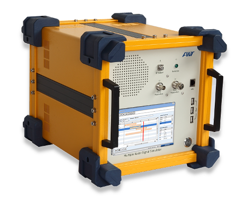
AWT(G) Radar Simulators generate a variety of Radar Signals. The Simulators are ideal for radar receiver testing and in training Radar Operators on object detection, recognition and Electronic Warfare (EW). The simulators offer variety of simulation capabilities; including Radar Warning Receivers (RWR), Missile Warning Receivers (MWR) and other Electronic Warfare (EW) Receivers.

Data Sheet Sales Offices eContact us
AWT’s Radar Simulator can generate up to 128 simultaneous CW or Pulsed signals. An intuitive graphical user interface (GUI) makes it easy to program signal parameters. Geographic Information System (GIS) tools are also available (optional). The receiving band(s) are developed to customer specifications. They are available in the range from 0.5 GHz and 40 GHz.
-
Replicates real radar signal characteristics (Frequency, Phase, Pulse, Modulation, SCAN).
-
Simulation Scenarios: AOA Simulation, Radar Activity, Virtual Missions.
-
Ideal for Electronic Warfare training and Radar receiver testing.
-
19” Standard Rack Mountable and Portable models are available.
-
Signal data library with up to 1024 entries.
 Portable Radar Signal Generators
For use in field, maritime and other applications where portability is crucial. The transmit antenna and amplifier are integrated, which allows the simulator and the receiver being tested, to be placed in separate locations.
19″ Rack-Mount Radar Signal Generators
Ideal for creating a variety of scenarios for use in extensive training. Also perfect for receiver testing applications.
Simulator & Threat Editor Software
RF Signal Parameter Management software runs on Windows operating systems. RF signals are composed of frequency, pulse and SCAN characteristics. All parameters are editable in an easy to use and clearly laid out user interface.
SCENARIOS
 AOA Simulation
-
DF test using Amplitude and Angle of the Antenna.
-
Antenna pattern measurement
-
Signal level change at scheduled time
Radar Activity
-
Search Radars
-
Acquisition Radars
-
Tracking Radars
Virtual Missions
Frequency
|
|
Range |
0.5 – 40 GHz |
|
NATO Bands |
C, D, E, F, G, H, I , J, K |
|
IEEE Bands |
UHF (upper), L, S, C, X, Ku, K, Ka |
|
Resolution |
1 MHz |
|
Accuracy |
1 kHz (higher accuracy on request)
2 MHz (VCO and DTO) |
|
Type |
Fixed, Agile (Sinusoid, Saw-Tooth, Triangular, Rectangular, Random), Hopping (up to 256 / sec) |
Pulse
|
|
Type |
CW, Stable, Jitter, Stagger (32 Steps), Dwell & Switch, Random |
|
Width Range |
0.05 – 225 us |
|
Repitition Interval |
1us – 1 sec
(longer possible) |
|
Density |
Up to 1,000,000 pulses / sec (PPS) |
|
FMOP |
Linear, Non-Linear
(FM Bandwidth depends on PW, 40 MHz max) |
|
PMOP Agile |
Bi-Phase, Quadratic-Phase |
Frequency Modulation on Pulse (FMOP)
|
|
Pattern |
Linear, non-Linear, Chirp up/down |
|
Agile |
Sine, Triangular |
|
Range |
10 – 512 MHz |
|
Accuracy |
1 MHz |
Phase Modulation on Pulse (PMOP)
|
|
Pattern |
Bi-Phase, Quadratic Phase |
|
Change Time |
< 50 ns |
|
Accuracy |
better than 20° |
SCAN
|
|
Types |
Electronic (Agile Beam), Conical, TWS, Steady, Sector, Lobe Switching, Circular, Helical, Raster, Bi-Directional, Use defined |
|
Rate |
50ms – 10 sec |
|
AM |
0 – 40 dB |
Output
|
|
Number of RF Signals per Bank |
1 CW + 1 Pulse Doppler Signal, or
1 CW + 16 Pulse Signals, or
17 Pulse signals |
|
Ports per Bank |
1 Vertical Polarization,
1 Horizontal Polarization,
1 Monitoring |
|
Power (Signal) |
> 15 dBm (other power levels on request) |
|
Monitoring Port |
> 5 dBm (other power levels on request) |
Communication Interfaces
|
|
Ethernet (IEEE 802.3), USB, RS-232 |