Solid-State Electrical Controlled Attenuators
发布时间:2025-11-4 9:28:0
加入购物车
Voltage Controlled Variable Attenuators up to 170GHz
|
Features |
 |
-
Low insertion losses
-
High isolation
-
Low cost
|
-
Low switching time
-
Full band operation
-
Easy to use
|
|
Applications |
 |
-
Alternative for polarization attenuators
-
Alternative for p-i-n modulators
-
AM of microwave signals
-
Power control
-
Lock-in detection systems
|
|
Description
|
|
|
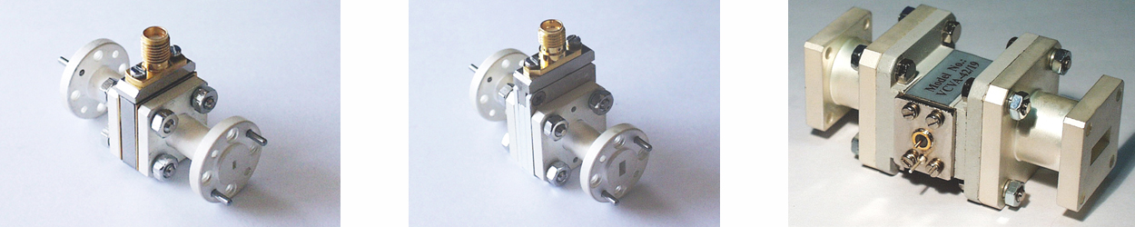
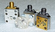
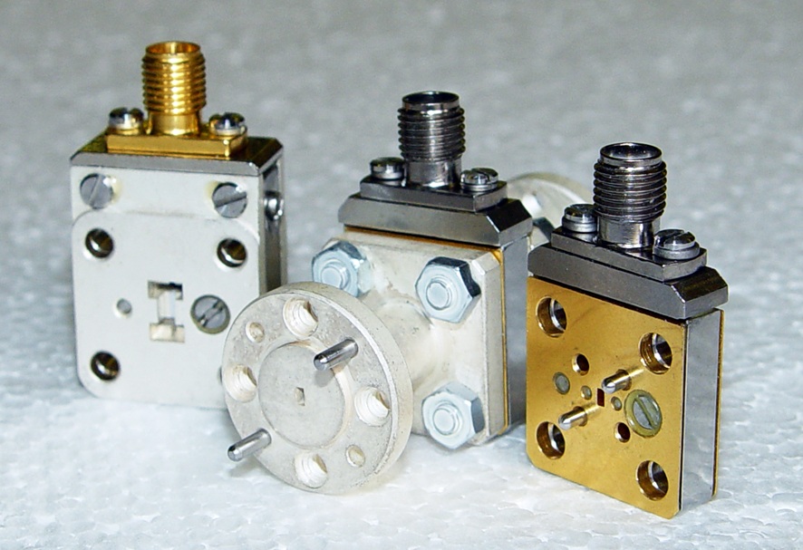
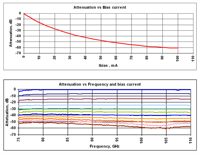
ELVA-1 series Voltage-Controlled Variable Attenuators VCVA is built on the base of PIN diodes as an active element. Modern technology allows to combine advantages of different types of attenuators and modulators in one device. Full band operation, accuracy, 60dB attenuation range and small insertion losses are comparable with specification for polarization attenuators. On the other hand a small switching time allows to use the device instead Faraday rotation ferrite modulators or ON/OFF type p-i-n modulators. The attenuators are designed as a gold covered waveguide section and have a high reliability. The basic unit is a current controlled attenuator. We propose also an external driver which provides a voltage current conversion and a switching time up to the 25 μsec. We supply each device with personal calibration characteristics. Typical characteristics for the VCVA-10 model are shown on two plots below: attenuation versus control voltage with fixed frequency and attenuation versus frequency with different control voltages. |
Specifications
|
Model |
VCVA-42 |
VCVA-28 |
VCVA-22 |
VCVA-19 |
VCVA-15 |
VCVA-12 |
VCVA-10 |
VCVA-08 |
VCVA-06 |
|
Frequency Band |
K |
Ka |
Q |
U |
V |
E |
W |
F |
D |
|
Range, GHz |
18-26.5 |
26-40 |
33-50 |
40-60 |
50-75 |
60-90 |
75-110 |
90-140 |
110-170 |
|
Wideband Version |
|
Bandwidth, % |
20 |
15 |
15 |
15 |
15 |
15 |
15 |
15 |
15 |
|
Insertion Loss, dB (typ) |
0,7 |
0,7 |
0,8 |
0,8 |
0,8 |
1 |
1 |
1 |
1 |
|
Isolation, dB (min) |
50* |
50* |
50* |
50* |
50* |
50* |
50* |
50* |
50* |
|
Peak Power, W(max) |
1 |
1 |
1 |
1 |
1 |
1 |
1 |
1 |
1 |
|
Switching Time, μsec ** |
100 |
50 |
50 |
50 |
50 |
50 |
25 |
25 |
25 |
|
DC Bias Input, mA |
100 |
100 |
100 |
100 |
100 |
100 |
100 |
100 |
100 |
|
Full band Version |
|
Bandwidth, % |
100 |
100 |
100 |
100 |
100 |
100 |
100 |
100 |
100 |
|
Insertion Loss |
1,0 |
1,8 |
2 |
2 |
2 |
2 |
2 |
3 |
3 |
|
Isolation, dB (min) |
50* |
50* |
50* |
50* |
50* |
50* |
50* |
50* |
45* |
|
Peak Power, W(max) |
1 |
1 |
1 |
1 |
1 |
1 |
1 |
1 |
1 |
|
Switching Time, μsec ** |
100 |
50 |
50 |
50 |
50 |
50 |
25 |
25 |
25 |
|
DC Bias Input, mA |
100 |
100 |
100 |
100 |
100 |
100 |
100 |
100 |
100 |
*The models with 60 dB Isolation are available upon request
**Guaranteed for Rise Time 0-90% RF and Fall Time 100-10% RF. Models with twice lower switching time are available upon request for the 50-170 GHz frequency range.
Mechanical specifications
ELVA-1 provides different issues:
- Flat mount flanges

- With extension waveguides